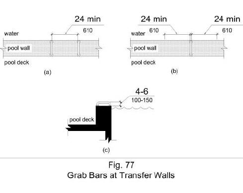
Figure 77 illustrates grab bars at transfer walls that are perpendicular to the pool wall and that extend the full depth of the transfer wall. Figure (a) shows in plan view two grab bars with a clearance between them of 24 inches minimum. Figure (b) shows in plan view one grab bar with a clearance of 24 inches minimum on both sides. Figure (c) shows in side elevation a height of the grab bar gripping surface 4 to 6 inches above the wall, measured to the top of the gripping surface.